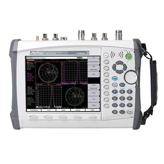
Anritsu VNA Master Vector Network Analyzer 5 kHz to 20 GHz
Performance and Functional Highlights :
- Broadband coverage of 5 kHz to up to 20 GHz
- True 2-path, 2-port Vector Network Analyzer
- Ultimate accuracy with 12-term error correction
- High Performance Handheld S-Parameters
- User-defined Quad Display for viewing all 4 S-Parameters
- Arbitrary data points up to 4001
- IF Bandwidth selections of 10 Hz to 100 kHz
- Directivity: >42dB up to 6GHz (all models) >36dB >6 GHz up to 20 GHz (all models)
- Supports Reciprocal Through Calibration types (SOLR, SSLR, SSSR)
- All models support waveguide measurements
- 350μs/data point sweep speed
- USB/Ethernet for PC data transfer and control
- Automate repetitive tasks via Ethernet & USB
- PIM Hunting •Field upgradeable firmware
- Operation to +55 ºC: full performance on AC or battery
- Store more than 4000 traces and setups in memory
- Portable: 4.5/4.8 kg (9.9/10.5 lb)•Time Domain (with gating) option
- Internal Bias Tee option•Vector Voltmeter option
- High Accuracy Power Meter option
- Differential option (Sd1d1, Sc1c1, Sd1c1, and Sc1d1)
- Secure Data Operation option for safe use in high security environments•GPS Receiver option
- Low Pass Stepped Response and Real Impedance graph type provide TDR functionality (standard capability with Time Domain option)
- Multiple display formats including Polar and Real Impedance
- Supports Anritsu USB Power Sensors
- 8.4 in, 800 x 600 high resolution, daylight-viewable TFT color display
- Complies with MIL-PRF-28800F Class 2, Certified for use in Explosive Atmosphere per MIL-PRF-28800F and MIL-STD-810G
VNA Functional Specifications :
Measurement Parameters S11, S21, S22, S12, (optionally: Sd1d1, Sc1c1, Sd1c1, Sc1d1)
Number of Traces Four: TR1, TR2, TR3, TR4
Trace Format Single, Dual, Tri, Quad, with Trace overlay capabilities
Graph Types Log Magnitude, SWR, Phase, Real, Imaginary, Group Delay, Smith Chart, Inverted Smith Chart (Admittance),
Log Mag/2 (1-Port Cable Loss), Linear Polar, Log Polar, Real Impedance, Imaginary Impedance
Domains Frequency Domain, Distance Domain, Time Domain with gating (Time Domain optional)
Frequency Start Frequency, Stop Frequency, Center Frequency, Span
Distance Start Distance, Stop Distance
Time Start Time, Stop Time
Frequency Sweep Type: Linear Single Sweep, Continuous
Data Points 2 to 4001 (arbitrary setting); data points can be reduced without recalibration.
Limit Lines Upper, Lower, 10-segmented Upper, 10-segmented Lower
Test Limits Pass/Fail for Upper, Pass/Fail for Lower, Limit Audible Alarm
Data Averaging Sweep-by-sweep
Smoothing 0 % to 20 %
IF Bandwidth (Hz) 10, 20, 50, 100, 200, 500, 1k, 2k, 5k, 10k, 20k, 50k, 100k
Reference Plane The reference planes of a calibration (or other normalization) can be changed by entering a line length. Assumes no loss, flat magnitude, linear phase, and constant impedance.
Auto Reference Plane Extension Instead of manually entering a line length, this feature automatically adjusts phase shift from the current calibration (or other normalization) to compensate for external cables (or test fixtures). Assumes no loss, flat magnitude, linear phase, and constant impedance.
Group Delay Aperture Defined as the frequency span over which the phase change is computed at a given frequency point. The aperture can be changed without re calibration. The minimum aperture is the frequency range divided by the number of points in calibration and can be increased to 20 % of the frequency range.
Group Delay Range < 180>
Trace Memory A separate memory for each trace can be used to store measurement data for later display. The trace data can be saved and recalled.
Trace Math Complex trace math operations of subtraction, addition, multiplication, or division are provided.
Number of Markers 12, arbitrary assignments to any trace
Marker Types Reference, Delta
Marker Readout Styles Log Mag, Cable Loss (Log Mag / 2), Log Mag and Phase, Phase, Real and Imaginary, SWR, Impedance, Admittance, Normalized Impedance, Normalized Admittance, Polar Impedance, and Group Delay, Linear Mag, Linear Mag and Phase
Marker Search Peak Search, Valley Search, Find Marker Value
Correction Models Full 2-Port, Full S11, Full S22, Full S11 & S22, Response S21, Response S12, Response S21 & S12, Response S11, Response S22, Response S11 & S22, One- Path Two-Port (S11,S21), One-Path Two-Port (S22,S12)
Calibration Types Flex, Standard
Calibration Methods Short-Open-Load-Through (SOLT), Offset-Short (SSLT), and Triple-Offset-Short (SSST), Short-Open-Load-Reciprocal (SOLR), Double- Offset-Short-Load-Reciprocal (SSLR), Triple-Offset-Short-Reciprocal (SSSR)
Calibration Standard Coefficients Coax: N-Connector, K-Connector, 7/16, TNC, SMA, and four User Defined coax typesWaveguide: WG11A, WG12, WG13, WG14, WG15, WG16, WG17, WG18, WG20, and four User Defined rectangular waveguide types
Cal Correction Toggle On/Off
Interpolation On/Off
Dispersion Compensation Waveguide correction that improves accuracy of distance-to-fault data by compensating for different wavelengths propagating at different speeds.
Impedance Conversion Support for 50Ω and 75Ω are provided.
Units Meters, Feet
Bias Tee Settings Internal, External, Off
Timebase Reference Internal, External
File Storage Types Measurement (.mna), Setup (.stp, with or without CAL), S2P (Real/Imag), S2P (Lin Mag/Phase), S2P (Log Mag/Phase), Text (VNA Only), CSV (VNA Only), JPEG
Ethernet Configuration DHCP or Manual (Static) IP configuration, 10/100 Base-T, RJ45 jack
Languages English, French, German, Spanish, Chinese, Japanese, Korean, Italian, Russian, Portuguese (Português)